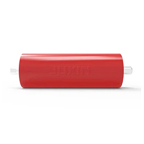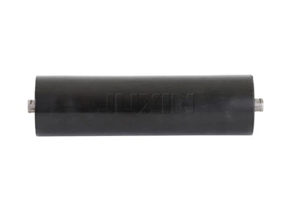
The answer to a mining belt conveyor choice is always only one: a proper custom mining belt conveyor system is developed from your actual route data, not from a catalogue page. Capacity, tension, carcass, take-up, splice and drive functions are only all together when they are sized to the same real conditions, in the specified order. Mining conveyor system engineering has an immediate payoff in terms of uptime and service life. Buyers of mining conveyor systems that follow this protocol rarely experience the same problems. The procurement process is consistent throughout the planning for the mining conveyor system, which starts here.
Failures of a mining conveyor system that can be attributed to a wrong initial decision are rarely minor. If left unaddressed, a mismatched specification compounds into:
- Each hour of unplanned downtime due to splice failure, mistracking or drive overload is a direct, measurable cost.
- Early replacement of belts, idlers and liners due to premature wear of these components long before a properly specified system.
- Safety risks due to insufficient or missing sensor packages, inadequate explosion-proofing or braking on steep gradients
- Energy waste due to the wrong tension profile working against oversized drives and high-resistance idlers
- Spillage and carryback that increase clean-up labour and degrade surrounding equipment over time
- OPEX losses are factored in, leading to budget overruns. The "savings" of a cheaper catalogue system are generally wiped out in the first year or two.
Mining conveyor design that totally ignores them pays them for it. Mining conveyor design can avoid all of these issues by following a single, consistent chain: map the route, convert the engineering data, and match each component to the engineering data.
| Decision Area | What It Covers | Why It Matters |
|---|---|---|
| Route & Safety Baseline | Zone-by-zone route log, mandatory safety sensors, entry-level capacity and frame load | Prevents the single costliest shortcut: specifying before route data exists |
| Capacity, Tension & Carcass | Normal/design/surge capacity, four-case tension calculation, fabric vs. steel-cord belt, take-up travel, splice method, drive-to-pulley matching | Converts route data into a buildable mining conveyor design |
| Ore-Driven Component Selection | Abrasion-resistant idlers and covers, impact beds, liner materials, cleaning systems, tracking, high-speed pulley balance | Matches hardware to what the ore itself does to the system |
| Environmental Specs | Explosion-proofing, corrosion protection, idler seals, dust control, high-temperature belt | Adapts the system to underground, corrosive, dusty, or hot conditions |
| Terrain & Layout | Incline drive/braking, rollback-resistant belt profiles, overland idler specs, frame design, maintenance access, power grid limits, transfer-point design | Fits the mechanical answer to the physical site |
| Cost Priorities | OPEX vs. CAPEX, high-ROI components, upgrade metrics, RFQ data sheets, supplier evaluation | Turns engineering choices into a defensible, lower-risk purchasing decision |
These steps are never omitted when designing mining belt conveyors. Mining conveyor design teams that follow this table from start to finish rarely revisit the same failure. Mining conveyor design, to put it simply, is the discipline that makes this guide work. Ultimately, custom conveyor solutions for mine challenges are a result of following this chain in its entirety, rather than stopping at the step that is most convenient to bypass. It is the custom conveyor solutions for mine challenges built on this chain that differentiate a conveyor that lasts and one that doesn't. Those who value this chain in the buying process of mining belt conveyors protect their budget and production schedule.
What Are the Baseline Standards for Mining Belt Conveyors?
Every mining conveyor system, regardless of ore type, must meet the same three baseline requirements: an accurate route map, a complete safety sensor package, and a defensible capacity calculation. Skipping any one of them is the most expensive shortcut in mining belt conveyor selection, because corrections made after fabrication cost far more than the extra week spent gathering data up front.
Why Map Mine Routes Before Custom Mining Belt Conveyor Solutions?
Before selecting components, it is essential to carry out extensive route mapping to prevent process mismatches and unnecessary capital expenditure. The most expensive shortcut in mining engineering is selecting catalogue conveyor components before the site-specific route geometry has been defined. A fully developed route map is the operational baseline for each conveyor section, including material state changes, elevation profiles, curved alignments, ambient temperature variations, inspection access corridors and dust containment areas.
When designing custom conveyor solutions for mine challenges, mapping the entire flowsheet into defined operational zones enables engineers to specify targeted configurations for each segment, rather than over-engineering the entire line. Consider a gold mining conveyor belt in a primary crushing circuit that sees severe lump impact, demanding specific impact absorption. Further downstream, overland transfers are focused on energy-efficient idlers. All mining belt conveyor systems must be adapted to their specific zone so that structural frames, belt carcasses and drive units work in perfect harmony across all mine conveyor components for highly abrasive ore conditions.
The conveyor zone log below is the basis for auditing mine routes before publishing the technical specifications:
|
Conveyor Zone Parameter |
Operational Scope & Technical Options |
Key Engineering Decision Factor |
|
Material Physical State |
Lump size distribution, moisture content, bulk density (0.8–2.8 t/m³) |
Determine belt width (500–2400 mm) and trough angle |
|
Topographical Profile |
Lift elevation, downhill decline angle, horizontal curves |
Dictate drive power, braking, and backstop requirements. |
|
Environmental Exposure |
Sub-zero ambient (-40°C), underground gas, salt fog |
Select FRAS belt, hot-dip galvanising, or sealed bearings. |
|
Operational Duty Cycle |
Continuous 24/7 run time, peak surge loading (t/h) |
Control idler L10 bearing life and pulley fatigue limits. |
|
Access & Inspection |
Single/double walkway, tunnel clearance, overhead truss |
Influence frame structure and maintenance lifter access |
The early establishment of this route log ensures that the mining conveyor system is built on verified field data. Each custom conveyor solution for mine challenges is guaranteed to provide long-term mechanical reliability through careful upfront mapping.
What Safety Sensors Does Every Mining Conveyor System Need?
The safety sensor package is mandatory and is part of the standard equipment, not an optional upgrade. A mining conveyor system is never evaluated on the basis of its belt and pulleys alone. Each line needs belt-sway (mistracking) switches, pull-cord emergency stops along the full walking length, slip or speed detectors to detect belt breakage or drive slip immediately, and a centralised PLC interlock. This ensures that one line of multiple conveyors starts in sequence and ends in reverse sequence. A reference framework such as ASME B20.1 is a useful checklist to check that none of these have been missed in the design of a proposed mining conveyor.
Mandatory safety sensors are a must for every high-capacity mining belt conveyor, which are installed as per the standard industrial safety guidelines, including ASME B20.1. These safety devices are integrated into the design of the mining conveyor in a multi-layered protective envelope:
Two-Stage Sway Switches (Misalignment Sensors)
Installed in pairs on the conveyor frame to sense belt drift to the side. An automated control-room alarm is triggered at stage-one deviation, and the mining conveyor system is instantly triggered at stage-two displacement to prevent major edge shredding.
Emergency Stops with Dual-Directional Pull-Cords
Dual-directional pull-cords are installed along all inspection walkways, featuring heavy-duty actuation cords that provide instant physical shutoff capabilities at any point along the line.
Non-Contact Speed and Slip Detectors
Proximity sensors monitor the rotation of the tail pulley as compared to the speed of the drive motor. An automatic shutoff is initiated if any speed difference indicates belt slippage to prevent the buildup of frictional heat and destruction of the belt carcass.
Rip and Tear Detectors
Inductive loops or ultrasonic sensors are located directly downstream of loading chutes to detect longitudinal belt punctures caused by tramp metal being caught. Connecting these sensors to an upstream metal detector for mining conveyor installations minimises damage to carcasses.
Thermal and Smoke Sensors
Infrared sensors are fitted on the main drive pulleys and underground transfer points to monitor the risk of premature combustion and spikes in bearing temperature.
The safety devices are integrated into a single PLC network to ensure the operational availability of critical equipment during harsh iron ore mining conveyor operations.
How Does Mining Conveyor Design Set Capacity and Frame Load?
The volume of a conveyor and the dynamic loads on the frame should be calculated based on the peak hour mass flow and material density, not the annual production figures. Because equipment is sized on the basis of average annual tonnage, spillage and structural overload will necessarily occur during peak surge conditions.
In a robust design, the volumetric capacity ($Q$) of a mining conveyor is determined by the cross-sectional load area ($A$), belt speed ($v$) and the bulk density ($\rho$).
$$Q=3600\cdot A\cdot v\cdot \rho$$
Standard mining belt conveyor configurations are designed to operate at speeds from 2.5 m/s to 6.5 m/s with belt widths from 800 mm to 2000 mm for primary mining duties. In calculations of loading on a structural frame, the static weight of the material, the mass of the belt carcass, dynamic impact forces at loading points and environmental wind or snow loads must be included. Dynamic stress evaluations ensure that structural deflection of impact idler conveyor frames for severe-duty mining belts is kept within strict tolerances, preventing frame deformation under heavy ore loading. By using these baseline load values, the advanced custom conveyor solutions for mine challenges precisely size drive motors and intermediate stringers.
How Do you Custom Conveyor Solutions for Mine Challenges?
The safety sensor package is a must and should be considered standard, not as an optional upgrade. A mining conveyor system is never judged on the belt and pulleys alone. Each line needs belt-sway (mistracking) switches, pull-cord emergency stops along the full walking length, slip or speed detectors to detect belt breakage or drive slip immediately, and a centralized PLC interlock. This ensures that one line of multiple conveyors starts in sequence and ends in reverse sequence. Reference frameworks such as ASME B20.1 can be a useful checklist for ensuring that a proposed mining conveyor design has not left out any of these.
How Do You Calculate Normal, Design, and Surge Capacity?
To avoid chute spillage and drive stall from unexpected tonnage spikes, it is important to establish three different capacity levels: normal, design, and surge. Material spillage from a mining conveyor system designed for the normal operating tonnage only will occur when volume surges occur at upstream crushers.
To ensure operational stability, engineering teams apply specific multiplier factors at each level of operational capacity:
Regular Functioning Capacity
The continuous mass flow rate (t/h) anticipated to take place during normal production cycles.
Design Capacity
This is the engineering standard for sizing drive motors, shaft diameters and structural frames and is calculated at 110% to 120% of normal load capacity.
Peak Surge Capacity
The peak surge capacity, rated at 125% to 150% of normal throughput, determines the cross-sectional dimensions of the chute, the height of the skirtboard, and the distance of the belt edge to absorb temporary surge feeds from a dump truck or crusher without overflow.
A proper balance of these three capacities in the overall design of the mining conveyor enables high-volume operations, such as an iron ore mining conveyor, to achieve maximum throughput without structural overload. Assessment of volumetric loading geometry and peak mass flow enables optimized custom conveyor solutions for mine challenges.
How Do You Calculate Mining Belt Tension Across Operating Cases?
Belt tension is the sum of several resistance sources, including lift (change in elevation), belt and idler friction over the entire length, resistance on horizontal curves, skirtboard friction at loading points, and cleaner drag against the belt face. Belt tension calculations must consider running, starting, stopping, and non-uniform loading conditions to prevent drive slippage and structural failure. The calculations for steady-state running tension do not account for the destructive dynamic tension spikes associated with emergency stops or full-load starts.
By using low-drag mine conveyor components for highly abrasive ore conditions, the overall running tension is significantly reduced. Transient acceleration tension during full-load motor startup can exceed 140% to 200% of the steady-state running tension. High-lift inclined lines require dynamic stress modelling to prevent reverse runaway, whereas maintenance crews deploying a heavy-duty belt lifter for large overland mine conveyors can safely relieve static tensions during routine splice maintenance.
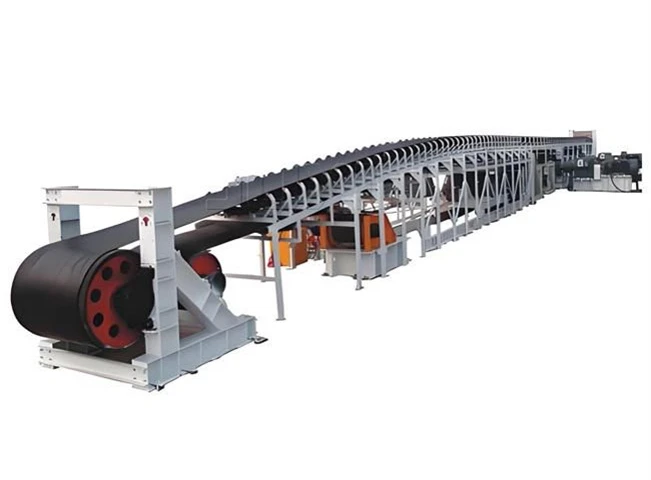
Fabric or Steel Cord: Which Mining Conveyor Belt Carcass Fits Your Route?
For high-tension, long-distance routes, the steel cord belt is the optimum choice. For short to moderate distance runs with frequent impact loading, the fabric (EP/NN) belt is the optimum choice. This is true because the two carcass types trade forgiveness for strength in opposite directions, as seen in the comparison below.
|
Mining conveyor belt structure |
Typical strength range |
Best-fit route |
Trade-off |
|
EP (polyester) fabric |
EP100–EP400, 100–400 N/(mm·layer) |
Short to moderate distance, frequent impact loading |
Lower splice and inspection demands; limited to shorter spans |
|
NN (nylon) fabric |
NN100–NN300, 100–300 N/(mm·layer) |
Impact-heavy transfer points, such as ore drop zones |
Higher elongation than EP; good shock absorption |
|
ST (steel cord) |
ST630–ST5400, 630–5400 N/mm |
Long-distance, high-tension overland mining belt conveyor lines |
Demands precise splice quality, wider inspection access, and careful drive layout |
There is always a sound mining conveyor belt structure to the carcass type. Not vice versa. The tension and distance profile is created in the previous step. There is no sense in using a steel-cord carcass for a short run, and a fabric carcass for a long overland high-tension route may cause early stretch and splice failure.
How Do You Size Take-Up Travel for Mining Belt Conveyor Routes?
The travel of the take-up must be set to allow for the permanent elongation of the belt over its service life. Fabric belts require a greater travel allowance than steel-cord belts. This is proportionately greater as fabric belts stretch more under sustained load. A second factor that adds to elongation on long routes is thermal expansion and contraction across the operating temperature range. This uses up additional take-up travel that a short indoor queue would never see. Screw take-ups are used for short, low-tension lines, gravity take-ups for medium lines with a fixed footprint, and automatic winch take-ups for long or high-tension mining belt conveyor systems where the take-up force needs to be automatically adjusted to changing conditions.
What Splice Method Keeps Mining Belt Conveyor Joints From Failing?
A well-made splice will outlast the belt body, and a poorly made splice will be the first point of failure on the line. Therefore, the splice method and quality control must be given the same engineering consideration as the belt itself. Steel-cord belts and any line fitted with high-pressure cleaners must be fitted with hot vulcanized splices made of material rated at or above the cover compound grade and with a documented cure record. The highly abrasive ore conditions cause mechanical fasteners to rapidly erode, creating catch points for primary belt cleaners.
For the high-integrity hot vulcanized joint, the tie-gum, strip rubber and cover stock compound grades (e.g. DIN-X or DIN-W) must be matched directly to the parent belt spec. Vulcanization must be carried out in a dust-free, sheltered enclosure and precise pressure and cure temperatures must be maintained, thus requiring the use of calibrated heating platens. For steel cord belt, the cords must be arranged in multi-stage step patterns to ensure total adhesion of rubber to steel. Strict splicing standards guarantee the structural integrity of each mining conveyor belt structure. With the implementation of routine splice inspection schedules, the direct protection of plant uptime and reduction of the mining conveyor downtime cost per hour are achieved, as well as minimizing catastrophic joint separations.
How Does Mining Conveyor Design Match Drive to Pulleys?
The minimum bending radius of the belt carcass should be dynamically matched to the pulley shell diameters, shaft deflection limits and drive motor sizing. Undersized pulleys with high-strength belt result in premature splice separation and core delamination due to the excessive inter-ply shear stresses generated.
The main drive units utilize high-efficiency electric motors (up to 800 kW), hard-tooth gear reducers and fluid couplings or VFDs (Variable Frequency Drives) for soft acceleration. High-tension drive pulleys require rubber or ceramic lagging. High-capacity gold mining conveyor belts lose power and slip drives unless they are ceramic lagged. Ceramic lagging increases the friction coefficient from 0.25 (dry rubber) to more than 0.40 under wet, muddy conditions. The drive torque is synchronized to the pulley shell geometry to optimize the total efficiency of the mining belt conveyor. The mining conveyor system runs at peak load with a perfectly matched, fully integrated drive package.
How Does Ore Shape Your Mining Belt Conveyor Choice?
Abrasion, impact, stickiness and belt speed all affect different components of the mining conveyor system in a negative way, so component selection should be driven by ore characteristics and not generic conveyor catalogues. The wear chain is described in the following sections in the order of occurrence on a working line. The iron ore mining conveyor belt and the gold mining conveyor belt are at opposite ends of the spectrum. In the former, coarse, highly abrasive run-of-mine rock is typically encountered at high tonnage, while the latter primarily handles finer, chemically treated material. In the latter case, corrosion resistance and wash-down cleanliness are as important as wear life. This section prevents the buyer from making the mistake of specifying a gold mining conveyor belt or an iron ore mining conveyor from the same generic template.
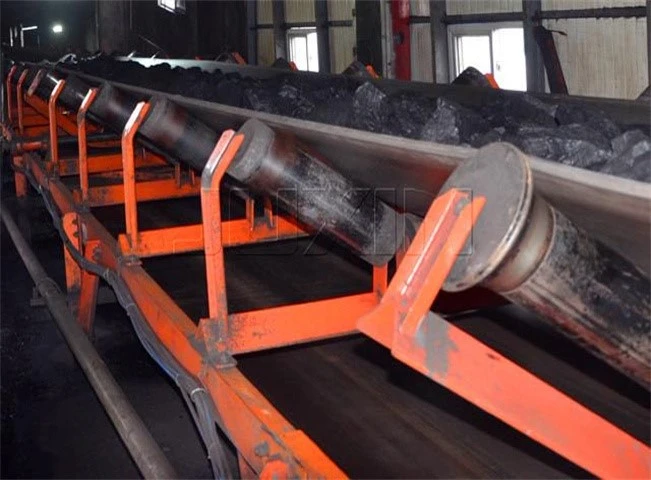
How Do You Prevent Rapid Mining Belt Conveyor Wear From Ore?
Abrasion is a continuous, line-wide load rather than a single-point event, necessitating the use of mine conveyor components for highly abrasive ore conditions on every wear surface, starting with the idler shell thickness and belt cover composition. Idler shells that are thicker (typically in the 3.5–5.0 mm range) and made of Q355B-grade steel have a significantly longer resistance to wear-through when in constant contact with ore. The DIN wear classification (W ≤90 mm³, X ≤120 mm³, Y ≤150 mm³) offers buyers a way of measuring and comparing cover compounds, instead of just looking at the vague term "wear resistant".
Cover thickness is not a simple case of "the thicker the better," and this is where many specifications go wrong. A cover that is constructed with a thickness that exceeds the application's requirements can increase rolling resistance and bending fatigue at small-diameter pulleys. Therefore, the life of the belt can be reduced instead of extended. The right approach is to combine mine conveyor components for highly abrasive ore conditions – reinforced idlers, a correctly graded cover compound – with a cover thickness that is proportional to the actual abrasion level measured in the field, not the maximum thickness that is possible.
What Stops Large Rock Impact From Tearing a Mining Belt Conveyor?
Impact beds of full length are the ideal solution for applications where large rock falls a considerable distance onto the belt, as opposed to impact idlers that are spot-mounted. That's because a bed spreads the impact load across a continuous support surface, rather than concentrating it between two sets of idlers. The impact bed structure is composed of a rigid steel frame and a rubber energy-absorbing layer. This prevents both puncture and internal belt delamination at the drop zone. Impact idler conveyor frames for severe-duty mining belts are the next best option when a full impact bed is not practical. These frames use rubber-disk or cushioned rollers on a reinforced frame to absorb drop energy at a single point instead of a continuous running surface. The best way to combat transfer-point damage on severe-duty lines is with a combination of a high-tear-resistance belt and impact beds or impact idler conveyor frames for severe-duty mining belts, rather than relying on the belt's strength alone.
Which Mining Conveyor Liners Handle High-Impact Points?
The selection of chute liner materials involves matching the appropriate metallurgical or synthetic substrate to the localized impact energy and sliding velocity.
The table below summarises the chute wear liner material performance in mining applications :
|
Liner Material Type |
Impact Resistance Rating |
Abrasion Resistance Rating |
Recommended Placement Zone |
|
Conclusion |
Ideal for high lump impact |
Best for continuous fine particle sliding wear |
Optimized per chute zone |
|
AR400 / AR500 Steel Plates |
High |
Moderate |
Primary chute backplates, rock boxes |
|
Chromium Carbide Overlay (CCO) |
Moderate |
Exceptional |
Secondary deflection plates, fine ore chutes |
|
Alumina Ceramic Tiles |
Low (brittle) |
Superior (ultra-hard) |
Slurry chutes, fine material transfer points |
|
Polyurethane / Rubber Panels |
High (elastic absorption) |
Good |
Skirtboard liners, impact zone side walls |
The life of the liner is optimized through the use of composite ceramic rubber liners in fine ore chutes and AR500 steel plates in primary dump boxes. One of the basic principles of advanced custom conveyor solutions for mine challenges is matching chute liners to material trajectories.
How Do You Clean Sticky, Wet Ore From a Mining Belt Conveyor?
A multi-stage cleaning system of primary polyurethane scrapers, secondary carbide blades, and return tail ploughs is required to effectively remove sticky carryback. Single-scraper systems are unable to clean wet, sticky ore, leading to material carryback buildup on return rolls and severe belt tracking errors.
Primary cleaners use flexible polyurethane blades mounted on the head pulley to remove 80% of the bulk carryback without damaging the belt surface. Hard tungsten carbide tips positioned downstream in secondary cleaners scrape off the residual fine films. The type of cleaner blades to be used depends on the type of belt joint. Mechanical splices require polyurethane blades, while vulcanized joints require tungsten carbide blades. To prevent material from falling into the return drum of any iron ore mining conveyor line, a V-plow scraper must be installed in front of the tail pulley.
How Does Mining Belt Conveyor Tracking Prevent Mistracking?
Mistracking is most often caused by off-center loading and uneven material distribution. The industry standard solution to mistracking is the use of self-aligning tracking idlers, which automatically correct the drift, rather than requiring constant manual adjustment. Typically, the heavier-duty tracking idlers have a polyurethane coating and are better suited to the higher lateral loads of a mining belt conveyor moving dense ore than the lighter-duty hardware for lower tonnage applications. Mistracking, which begins at one point in the queue, will often manifest itself as edge wear at some other location. Tracking correction should be checked at the loading zone and return run.
How Does High-Speed Transport Affect Mining Conveyor Pulleys and Rollers?
Dynamic pulley balancing and low-runout idler assemblies are required to prevent vibration fatigue when running conveyor belt at high velocities (over 4.5 m/s). High rotational frequencies of out-of-round pulleys generate intense centrifugal forces that accelerate fatigue across weld seams and bearing housings.
Pulleys designed for high-speed operation shall be dynamically balanced and shall have radial runout tolerances of $\le 0.75\text{ mm}$. Heavy-duty idlers require C3 internal clearance bearings, multi-stage labyrinth seals and shell runout tolerances less than 0.5 mm. The mining conveyor design includes precision balancing for quiet operation and to increase bearing life to over 30,000 hours in any high-speed mining conveyor system.
How Do Extreme Mine Environments Change Mining Conveyor Specs?
Each of the following factors-underground gas risk, corrosion, dust, and temperature-requires a unique, tailored response, rather than a single, generic upgrade package. Environment, not just ore, necessitates significant modifications to a mining conveyor system.
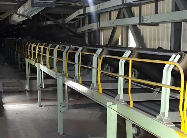
What Explosion-Proof Specs Do Underground Coal Mines Require?
Underground coal mining operations require the use of explosion-proof electric drives with flame-retardant anti-static (FRAS) conveyor belt certified to MT 914. Static charges from standard rubber belts are a major fire hazard in underground coal seams with combustible coal dust and methane gas.
FRAS belt is manufactured from solid woven PVC or PVG cores that are impregnated with fire-resistant compounds. The rubber covers undergo stringent tests for surface electrical resistance and flame propagation to comply with national safety standards such as MT 914. Electric motors and sensor housings must be explosion-proof isolated. Custom conveyor solutions for mine challenges that are approved for underground use ensure full safety compliance at all times.
How Do You Protect Mining Belt Conveyor Structures From Corrosion?
Hot-dip galvanized frames, FRP or GRP walkways, and heavy-duty anti-corrosion coatings are the usual solution to acidic mine water or salt-fog exposure. Carbon steel will quickly degrade in either situation without treatment. This is a particularly important checklist item for potash and other chemically aggressive ores. A frame or walkway that looks fine in a dry demo environment can corrode through in a fraction of the expected service life when exposed to acidic drainage or salt spray. For mining industry applications that are close to lubricant-heavy equipment, such as crusher stations or gearbox platforms, an oil-resistant conveyor belt is required because standard rubber compounds degrade over time when exposed to oil. This belt offers an additional layer of protection that structural coatings alone do not offer.
Which Idler Seals Stop Bearing Failure in Dust and Water?
Multi-stage labyrinth seals are the primary remedy for dusty or wet underground conditions and have been proven by a 500-hour water-spray test. This is because dust and moisture ingress into the bearing housing is the most common cause of idler seizure. The labyrinth seal keeps most contaminants out of the bearing. For heavy-duty or constantly submerged applications, Taconite-style seals are often used. They have grease purged through them constantly to flush contaminants away from the bearing instead of simply preventing entry. The service life possible is directly tied to the quality of the idler seal. For instance, a unit rated at approximately 20,000 hours with standard sealing can realistically see its life extended to 30,000 to 50,000 hours by employing upgraded sealing and tighter manufacturing tolerances.
How Do You Control Mining Belt Conveyor Dust at Transfer Points?
Dual-seal skirtboarding (enclosed tubular belt profiles) or extended settling zones are required to control airborne dust emissions at transfer chutes. Uncontrolled dust spillage leads to significant hazards to health and accelerated mechanical wear of components in the surrounding environment.
Dual-seal skirting has an inner rubber strip which is primarily in keeping bulk material on the belt, while an outer polyurethane blade is flexible to seal fine airborne dust. The seal material is important, but so is the right skirtboard gap. If the skirting is too tight, it will drag on the belt and increase wear. If the skirting is too loose, dust and fines will leak out no matter how good the seal is. Settling zones downstream of loading points must be of sufficient length to allow the dust to settle before exiting the skirted area. Pipe conveyors are fully enclosed and create a continuous rubber tube that fully covers the material along the transport path in environmentally sensitive zones. Regular dust control maintenance increases the reliability of any mining conveyor system.
How Do You Select High-Temperature Mining Conveyor Belt?
In selecting a belt for hot material, the temperature of the ore itself should be taken into account, not the surface temperature of the belt, as the two may be quite different and a belt sized on the basis of surface readings alone may still be found lacking due to the continued internal heat exposure. Unlike SBR compounds, which are limited to relatively low continuous temperatures, a heat-resistant conveyor belt for mining operations carrying sintered ore or clinker usually relies on an EPDM or EPM cover compound, which can withstand continuous service in the region of 150–200°C. Reference standards such as ISO 4195 accelerated-aging testing and T150/T200 heat ratings allow buyers to consistently compare quotes for heat-resistant conveyor belts for mining across suppliers.
Insulating shields at transfer points and slightly decreased idler spacing in hot zones combine to manage belt sag and heat buildup at the component level. The two most prevalent high-temperature failure points are flex cracking at small diameter pulleys and cover-to-carcass bond strength. This high-temperature case applies mainly to the handling of sintered ore, clinker and similar hot materials, but the majority of general ore-conveying applications can be ignored entirely.
How Does Mine Terrain Change Your Mining Conveyor Design?
The terrain changes the mechanical answer, not the underlying math. The tension and capacity calculations from the previous section are unchanged; the only change is the hardware required to safely move the load a distance, on a slope, or through a confined space.
What Drive and Braking Do Steep Inclines or Declines Need?
Electro-hydraulic braking systems are required on downhill decline lines to prevent gravitational runaway, and mechanical low-speed backstops are required on steep inclined conveyors operating above 12°.
Low-speed mechanical roller backstops mounted on the drive pulley shafts of steep incline routes will engage instantaneously in case of a power failure, locking the drive system and preventing material from rolling back down the incline. But downhill decline lines are regenerative power in continuous operation. Their electro-hydraulic block brake systems control deceleration ramps at full load to avoid runaway overspeeds. The terrain profile must be considered in the selection of the drive and brake components to obtain full operational control of a mining conveyor system.
Which Mining Belt Conveyor Profiles Stop Incline Rollback?
When elevating bulk material on inclines greater than 18°, Chevron patterned belt or corrugated sidewall belt profiles are required to prevent rollback of material.
Chevron belts with moulded rubber studs from 5 mm to 32 mm provide material lift up to 30°. Corrugated sidewall belt with cross-cleats allows high-angle inclines up to 90° vertical lifts in confined mine shafts. Scraper Compatibility: Scraper compatibility is a big factor in cleat selection. Chevron patterns require specialized finger scrapers or rotary brush cleaners to clean carryback. Matching profile geometry to incline angles is a crucial requirement when delivering custom conveyor solutions for mining challenges. The matching of the profile features guarantees the transport efficiency of the mining belt conveyor.
How Do Overland Routes Change Mining Conveyor Idler Specs?
For the overland conveying routes, ultra-low resistance idlers (≤1.8 N to 2.2 N) are needed to reduce power consumption and overall tension of the system.
A decrease of 0.5 N in the idler rotational resistance results in an electricity saving of about 8,000 kWh per kilometre of conveyor line per year. Intermediate channel or wire-rope framing is used in overland conveyor structures to accommodate ground topography and to absorb thermal expansion stresses. Spacing the carrying idlers out to 1.5-2.0 meters reduces the rolling resistance while keeping the belt sag within the CEMA limits. High-efficiency impact idler conveyor frames for severe-duty mining belts at loading points maintain structural integrity over long overland routes. For the most demanding overland applications, a heavy-duty belt lifter for large overland mine conveyors allows safe, controlled belt handling during installation, splicing and major maintenance work where manual handling of a wide, heavy belt section is neither practical nor safe.
Which Mining Conveyor Frame Designs Fit Tunnels or Pits?
The underground entries are confined and require low-profile modular channel frames. The open-pit routes are wide span and require deep lattice truss structures.
The table below compares frame designs of open-pit mines and underground tunnels:
|
Frame Design Category |
Structural Profile & Material |
Span Capability |
Target Mine Environment |
|
Conclusion |
Compact for tight clearances |
Rigid for wide elevated spans |
Environment-specific match |
|
Channel Steel Frame |
C-channel stringers, floor-mounted posts |
Short spans (3.0 m) |
Underground entries, low-headroom galleries |
|
Lattice Truss Frame |
Deep structural angle / tube welded truss |
Long spans (12.0–30.0 m) |
Overland elevated runs, pit-to-plant crossovers |
|
Floor-Mounted Modular |
Bolt-together pre-assembled modules |
Variable floor alignment |
Rapidly expanding pit floors, temporary runs |
Fixed clearance also means that parts of the underground tunnels often need a frame that is narrower and lower-profile, but still allows for inspection access. Instead, open-pit, overland sections must span longer, unsupported distances cost-effectively. This requires a truss-style frame that efficiently distributes the load over a wide span between support points. Choosing the right structural framing makes the installation process easier and ensures stable support of the entire mining conveyor belt structure.
What Other Design Factors Affect Mining Conveyor Systems?
When buying a mining conveyor system, the operating costs should be prioritized over the purchase price. This is because the energy and maintenance costs over the multi-year operating life of a mine site are much higher than the initial savings from a cheaper purchase. The following sections apply that principle to a practical purchasing process.
How Does Maintenance Access Shape Conveyor Frame Layout?
Structural frame layouts can include quick-release component mounts and minimum 800 mm walkways to dramatically reduce maintenance downtime. • Limited clearances around drive stations and transfer points impede routine maintenance and increase outage durations.
Maintenance-friendly frames incorporate slide-out impact beds, swing-out cleaner brackets, and rigging hooks designed for that purpose. For safe lifting of tensioned belt during idler roll replacements, multi-kilometre overland line mine sites use a heavy-duty belt lifter for large overland mine conveyors. Because of the quick availability of parts, the overall mining conveyor downtime cost per hour metrics suffer significantly. Including accessibility in custom conveyor solutions for mine challenges is essential to maximizing equipment availability.
How Do Power Grid Limits Affect Motor and VFD Choice?
When deciding to purchase a mining conveyor system, the cost of operation should be less than the cost of purchase, since the costs of energy and maintenance over the multi-year operating life of a mine site are far greater than the initial savings from a cheaper purchase. The following sections translate that into a practical buying process.
How Do You Design Transfer Points to Match Crushers?
In the design of transfer chutes downstream of primary crushers, tramp metal removal and Discrete Element Method (DEM) flow modelling are required to avoid chute jams and belt tears. Crushers that drop material vertically onto belt can cause serious carcass damage and material spillage.
Proper integration of crusher discharge points requires a five-stage design sequence:
DEM Trajectory Simulation
Modelling of ore trajectories to create curved rock-box chutes that align the velocity of the material to the direction of the belt.
Tramp Metal Interception
Install an overhead cross-belt magnet and an inline metal detector for mining conveyor setups before transfer points to remove steel teeth and drill rods.
Speed Vector Matching
This is the modification of the chute geometries to have the velocity of the material impact the belt equal to the forward belt speed, which is between $2.5 and 6.5 m/s.
Impact Bed Alignment
Continuous impact beds are positioned directly under the drop zone for the load of falling ore.
Dust Containment Skirting
Dual seal skirtboards extended downstream to allow airborne fines to settle out before exiting the enclosure.
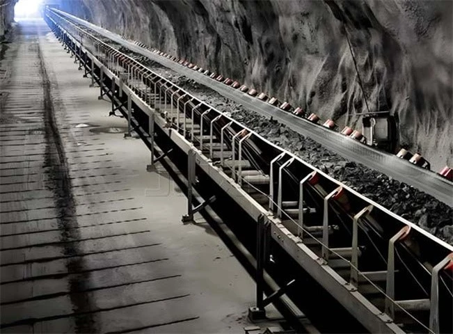
This structured transfer design safeguards the downstream lines of any iron ore mining conveyor system.
How Should Cost Priorities Drive Your Conveyor Choice?
When deciding to buy a mining conveyor system, operating costs should be more important than the purchase price. This is because the energy and maintenance costs over the many years a mine site is in operation are much higher than the initial savings from a cheaper purchase. The next sections put that principle into a practical buying process.
Why Must OPEX Outweigh Initial Conveyor Purchase Price?
Over the operating life of a conveyor, the cumulative cost of energy and downtime losses significantly exceeds the original purchase price. Therefore, the decision to purchase should be guided by OPEX, not CAPEX. A slightly higher initial cost for better components consistently demonstrates that it pays off quickly when mining conveyor downtime cost per hour is taken into account. Mining conveyor downtime cost per hour varies depending on the operation, but even a conservative estimate is typically dwarfed by the difference in price between a standard and an upgraded component package.
How Do You Select High-ROI Components to Lower TCO?
To lower the Total Cost of Ownership, we need to focus on high ROI components like ceramic pulley lagging, heavy-duty impact beds and low-drag idlers.
Targeted component upgrades to achieve high financial return:
Low-Drag Idlers
Idlers with a rotational resistance of $\le 1.8\text{ N}$ and lower energy consumption, offering you continuous electricity savings over a 15-year service life.
Engineered Impact Beds
Replace traditional rollers with heavy-duty impact beds to eliminate impact tears and triple the life of a gold mining conveyor belt carcass.
Ceramic Pulley Lagging
Prevent drive slippage, protecting drive motors and minimizing belt cover wear.
Standard off-the-shelf components are best for low-impact, low-wear sections of the line. Custom components, supported by a stocked spare-parts position, are appropriate for critical transfer points where the cost of downtime is highest. You can better control the total cost of ownership by intentionally combining standard and custom components throughout the entire mining conveyor system, rather than using one or the other.
Which Metrics Prove Your Mining Belt Conveyor Upgrade Paid Off?
It's an impression of before and after, not proof. The real proof that an upgrade has paid off is a documented baseline that has been monitored for at least two full quarters post-commissioning. Useful baseline metrics include belt-related OEE loss; mean time between failures (MTBF) for splice and loading-zone interventions; and the full TCO breakdown across energy, parts and labour. It is recommended to monitor the following three continuous indicators every month: Energy intensity (kWh/tonne moved) Wear rate (millimetres/thousand operating hours) Number of stoppages related to carryback (per month) All of these numbers add up to "the upgrade feels better" being a documented, valid result.
What Belongs on an RFQ Data Sheet for Mining Belt Conveyor Quotes?
By setting up a standard Request for Quotation (RFQ) data sheet that covers operational capacities, material properties, and route geometry, we make sure that vendor proposals can be compared on an equal footing. When RFQ documents are vague, suppliers have to make unverified assumptions, resulting in non-comparable bids.
The following mandatory parameters have to be included in an engineering-grade RFQ data sheet:
Process and Location Parameters
Operational zone ID, ambient temperature range, center-to-center distance and height profile.
Material properties
Abrasiveness, moisture content, particle size distribution and bulk density (t/m3).
Capacity Tiers
Normal, design (120%), and peak surge (150% t/h).
Mechanical and Belt Specs
The necessary tension rating (N/mm), carcass selection (EP/ST), speed (m/s) and take-up system type.
Cover Rubber Specification
DIN wear grade (W/X/Y), FRAS MT 914 certification, heat/oil resistance rating.
Auxiliary Systems
Metal detector systems, sway/slip switches, impact beds and cleaning systems.
The process of converting a collection of conflicting quotes into a truly comparable shortlist is to have each vendor set out their assumptions and exceptions in the same data sheet format, following this.
How Do You Evaluate a Mining Conveyor System Supplier's Engineering Depth?
The best predictor of a supplier's failure rate after installation is not just what they quote. It is the depth of their engineering. Therefore, the evaluation process must include factors such as their in-house engineering capability, metallurgical testing capability, field-service response time, lead time, and a history of similar mining projects. Price comparison alone does not reflect the most critical factor once a line is operational. Whether the supplier's engineering work was verified before fabrication or was only found to be inadequate after startup. Even if the quoted price is not the lowest on the table, the lower-risk option is always a mining belt conveyor built by a supplier with proven engineering depth in capacity, tension, carcass and drive calculations.
CTA
Mining belt conveyor performance is not a detail to leave to chance - it is the backbone of every ton your operation moves. A conveyor specified from real route data, matched belt carcass, and verified drive calculations keeps ore flowing instead of stacking up at a stalled transfer point. For mine operators, this translates directly into fewer unplanned stops, lower energy spend per ton, and a measurably longer service life across idlers, pulleys, and splices. Partnering with an engineering team that builds every system around your actual flowsheet, not a generic catalogue entry, means your conveyor is ready for the abrasion, impact, and environmental conditions unique to your site from day one. Request a route-based specification review today, and start building a mining conveyor system engineered to perform under your real operating conditions, not a textbook average.